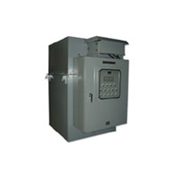
Liquid Rheostat
PRODUCT MAP VIEW
- Brake
- Cable Reel
-
Lifting Magnet
- ALL
- Electro Magnet
- Electro Permanent Magnet
- Magnetic Separator
- Resistor
- Particle Accelerating Magnet
- Super Conducting Magnet
-
Drive & Control System
- ALL
- Control Unit
- ALL
- TSA-002B
- Under Current Detector
- Control Panel
- Noncontact MC
- Motor Brake Unit
- Moter Speed Detector
- New Battery Charger(TDC-9030)
- Battery Charger
- New Brake Controller (TBC-6020A)
- Brake Controller(TCBⅡ)
- New Magnet Control Unit(TDR)
- Magnet Control Unit(FDR)
- wound rotor motor Controller(FDA)
- Inverter
- Battery Status Monitor(TDP-BM)
- Control System
- CMMS
-
Others
- ALL
- Limit Switch
- ALL
- Differential Switch (TL-D)
- Combination Type (TL-TCN)
- O.S. & Pulse Generator (TL-PC)
- Over Speed Switch (TL-C2)
- Digital Over Speed Switch (TL-OP)
- Digital Over Speed Switch (TL-OPT)
- Screw Type (TL-S)
- Weight Type (TL-G2)
- Weight Type (TL-G)
- Lever Type (TL-L6)
- Lever Type (TL-L5)
- Lever Type (TL-LC)
- Lever Type (TL-LB)
- Lever Type (TL-LA)
- Worm Gear Type (TL-WR8N)
- Worm Gear Type (TL-W4)
- Pantagraph
- Controller

- Resistor
- Liquid Rheostat
- FEATURE
- Three sets of moving and fixed electrodes are installed in steel plate tank, and individually held in insulating cylinders, and thus separated each other.
The fixed electrodes are fixed with lead bolt insulated by high voltage insulators while the moving electrodes are moving simultaneously in the electrolyte by motor or via manual. Control of operation, terminal box of motor, peep hole, thermometer, etc, are all provided on the steel plate cover. The inside can easily checked with lift of cover.
A level gauge is provided on the side of tank near tops where it can easily be found. In the mechanic control, limit switches are assembled to detect the resistance values in maximum (represented by the highest position of moving electrodes) and minimum(represented by the lowest position).